FM transmitter manuals are crucial guides for hobbyists and engineers, detailing construction, operation, and troubleshooting of these devices, enabling successful projects.
Understanding these documents unlocks the potential for building compact stereo transmitters and exploring the fundamentals of FM technology, as demonstrated in DIY labs.
What is a Wireless FM Transmitter?
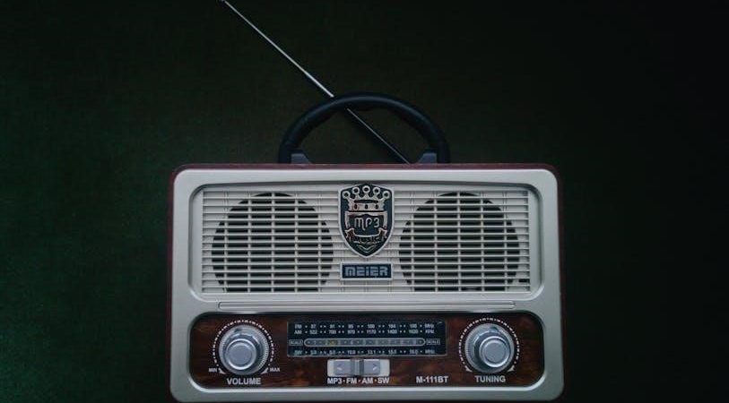
A wireless FM transmitter is an electronic device that takes audio signals and broadcasts them over radio waves using the Frequency Modulation (FM) method. These devices, often built by enthusiasts following a manual, convert audio – like music or speech – into a radio frequency signal.
Historically, FM transmission emerged as an improvement over earlier technologies like Amplitude Modulation (AM), offering better audio fidelity and less susceptibility to interference. Modern transmitters, detailed in their respective manuals, can range from simple, low-power units for personal use to more complex systems for broadcasting.
The core function, as explained in a typical manual, involves modulating a carrier wave with the audio signal, then amplifying and radiating it via an antenna. DIY projects often focus on building these transmitters using readily available components, guided by the instructions within the manual.

Why Consult a Manual?
Consulting a wireless FM transmitter manual is paramount for successful construction and operation. These manuals provide detailed schematics, component lists, and step-by-step instructions crucial for avoiding errors and ensuring optimal performance. They bridge the gap between theoretical knowledge and practical application, especially for DIY projects.
A manual safeguards against potential hazards, outlining safety precautions related to soldering, power supplies, and RF radiation. Furthermore, it’s the primary resource for troubleshooting common issues like signal distortion or limited range, offering solutions based on specific transmitter designs.
Understanding the manual’s technical specifications – frequency range, power output, and modulation type – is vital for legal and effective operation. Ignoring the manual can lead to non-functional circuits or even damage to components.
Understanding FM Transmission Basics
FM transmission relies on modulating a carrier wave with audio signals, a process detailed in transmitter manuals, enabling wireless audio broadcasting and experimentation.
Frequency Modulation (FM) Explained
Frequency Modulation (FM), as explained within a wireless FM transmitter manual, involves altering the frequency of a carrier wave in direct proportion to the amplitude of the audio signal. Unlike Amplitude Modulation (AM), FM prioritizes a constant amplitude, resulting in superior noise immunity and clearer audio quality.
Transmitter manuals often illustrate how this process works, detailing the circuitry responsible for shifting the carrier frequency. The amount of frequency deviation – the extent of the frequency change – determines the signal’s strength and clarity. Proper understanding of FM principles, guided by the manual, is essential for building and optimizing a transmitter for effective wireless communication. This technique was a major advancement over earlier methods.
The Role of Carrier Waves
A wireless FM transmitter manual emphasizes the fundamental role of the carrier wave. This is a high-frequency signal, generated by the oscillator circuit, which acts as the foundation for transmitting audio information. The manual details how the audio signal modulates, or alters, this carrier wave’s frequency – the core principle of FM transmission.
Without a stable and properly tuned carrier wave, as described in the manual, effective transmission is impossible. The carrier’s frequency dictates the radio station you tune into. Understanding its characteristics, including frequency and power, is crucial for building a functional transmitter. The manual will guide you through generating and maintaining this vital signal.
Stereo vs. Mono FM Transmission
A wireless FM transmitter manual often dedicates sections to explaining the differences between stereo and mono transmission. Mono transmission, simpler to implement, sends audio information using a single channel. Stereo, however, utilizes two channels – left and right – to create a more immersive listening experience.
The manual will detail how stereo FM transmission requires more complex circuitry, including a multiplexer to combine the left and right audio signals with a pilot tone. This pilot tone allows the receiver to decode the stereo information. Understanding these distinctions, as outlined in the manual, is vital for building a transmitter capable of delivering high-fidelity audio.

Components of a Typical FM Transmitter
Manuals detail essential components: oscillators for signal generation, modulators to imprint audio, antennas for transmission, and power supplies for operation—critical for functionality.
Oscillator Circuit
FM transmitter manuals emphasize the oscillator circuit as the heart of signal generation. These manuals typically illustrate various oscillator designs, often utilizing CMOS logic for simplicity and stability, as seen in DIY transmitter projects.
The manual will explain how the oscillator creates a precise VHF carrier wave, crucial for FM transmission. Detailed schematics and component lists are provided, guiding users through the construction process. Understanding the oscillator’s frequency stability is paramount, as drift impacts signal quality.
Manuals often include troubleshooting tips for oscillator-related issues, such as frequency inaccuracies or a complete lack of oscillation. They may also detail adjustments for fine-tuning the carrier frequency, ensuring compliance with local regulations.
Modulator Circuit
FM transmitter manuals dedicate significant attention to the modulator circuit, explaining how audio signals are superimposed onto the carrier wave. These manuals detail the techniques for achieving frequency modulation (FM), where audio variations alter the carrier frequency.
Schematics illustrate the modulator’s design, often employing varactor diodes to achieve frequency control proportional to the audio input. Manuals emphasize the importance of minimizing distortion during modulation, crucial for high-fidelity audio transmission.
Troubleshooting sections address issues like excessive distortion or weak modulation, providing guidance on component adjustments and potential replacements. Understanding the modulator’s role in signal quality is key, as it directly impacts the listener’s experience.
Antenna Design & Importance
FM transmitter manuals consistently highlight the antenna as a critical component, directly impacting transmission range and signal clarity. Manuals detail antenna types – dipole, monopole, and variations – explaining their radiation patterns and impedance matching requirements.
Proper antenna length calculations, often based on the carrier frequency, are provided to maximize efficiency. Diagrams illustrate construction techniques, emphasizing the importance of precise dimensions and quality materials.
Troubleshooting sections address issues like weak signal strength, often linked to antenna mismatch or poor construction; Manuals stress the need for a correctly tuned antenna to effectively radiate the modulated signal, ensuring reliable reception.
Power Supply Considerations
FM transmitter manuals dedicate significant attention to power supply requirements, emphasizing voltage stability and current capacity. They specify acceptable voltage ranges – typically 3V to 12V DC – and detail the current draw of various transmitter circuits.
Manuals often caution against voltage fluctuations, which can distort the signal or damage components. Filtering and regulation circuits are frequently recommended to ensure a clean power source.
Battery operation is often discussed, including battery type recommendations and expected operating time. Troubleshooting sections address power-related issues, like insufficient voltage or excessive ripple, impacting transmission performance.

Decoding a Wireless FM Transmitter Manual
FM transmitter manuals require careful interpretation of safety warnings, technical specs, and diagrams to successfully build, operate, and troubleshoot these electronic devices.
Safety Precautions
Prioritize safety when working with FM transmitter circuits. Manuals often detail crucial warnings regarding power supply voltages, potentially lethal if mishandled. Always disconnect power before making any connections or modifications to the transmitter.
Be mindful of RF exposure; while low-power transmitters pose minimal risk, prolonged exposure to radio frequency radiation should be avoided. Ensure proper grounding to prevent electrical shock and reduce interference. Soldering irons reach high temperatures – use caution and wear appropriate eye protection.
Component handling requires care; some parts may be sensitive to static electricity. Read the manual thoroughly before beginning any assembly or testing procedures, understanding all potential hazards. Never operate a damaged transmitter, and always follow local regulations regarding radio transmission.
Technical Specifications
FM transmitter manuals meticulously list key technical specifications. These include the operating frequency range, typically 88-108 MHz for FM broadcasting. Transmission power, often measured in milliwatts (mW), dictates range. Modulation type (stereo or mono) is clearly stated, alongside signal-to-noise ratio (SNR) indicating audio quality.
Supply voltage requirements are vital for proper operation, alongside current consumption. Harmonic emissions, a measure of unwanted frequencies, are often specified. Antenna impedance, usually 50 ohms, ensures efficient signal transfer. Operating temperature range defines environmental limits.
Manuals detail input sensitivity for the audio signal and frequency response characteristics, impacting sound fidelity.
Block Diagram Interpretation
FM transmitter manuals prominently feature block diagrams, visually representing the signal flow. These diagrams break down the transmitter into functional units: oscillator, modulator, amplifier, and antenna. Understanding these blocks is crucial.
The oscillator generates the carrier wave. The modulator combines the audio signal with the carrier. Amplifiers boost the signal strength. The antenna radiates the modulated signal. Arrows indicate signal direction.
Manuals explain each block’s purpose and interaction. Identifying key components within each block aids troubleshooting. Recognizing feedback loops and control signals enhances comprehension. Mastering block diagram interpretation unlocks a deeper understanding of the transmitter’s operation.
Pinout Diagrams & Component Identification
FM transmitter manuals dedicate sections to pinout diagrams, essential for correct component placement and wiring. These diagrams detail each pin’s function on ICs and other components, preventing damage and ensuring proper operation.
Component identification is equally vital. Manuals list all parts with clear descriptions and often include datasheets. Recognizing resistor color codes, capacitor values, and transistor types is crucial for assembly.
Carefully matching pin numbers and component values to the schematic is paramount. Incorrect connections can lead to malfunction or component failure. Thoroughly studying these diagrams before soldering minimizes errors and guarantees a functional transmitter.

Troubleshooting Common Issues
FM transmitter manuals provide systematic solutions for problems like no signal, distorted audio, or limited range, guiding users through diagnostic steps.
No Signal Output
A lack of signal, as detailed in FM transmitter manuals, often stems from power supply issues; verify voltage levels and polarity are correct. Inspect the oscillator circuit for component failures – capacitors, resistors, or the oscillator IC itself – using a multimeter.
Check antenna connections; a loose or damaged antenna drastically reduces output. Confirm the modulator circuit is functioning, ensuring audio input is present and properly amplified. Review the manual’s troubleshooting section for specific test points and expected voltage readings.
Carefully examine soldering joints for cold solder or shorts, which can interrupt signal paths. Finally, ensure the transmitter is operating within legal frequency limits, as exceeding them may trigger automatic power reduction or shutdown features.
Distorted Audio
Distorted audio, according to FM transmitter manuals, frequently indicates issues within the modulator circuit. Verify the audio input signal isn’t overdriving the modulator, causing clipping. Check the pre-emphasis settings; incorrect settings can lead to noticeable distortion, especially at higher frequencies.
Inspect the modulator’s components – diodes, transistors, or integrated circuits – for signs of damage or malfunction. Ensure proper biasing of the modulator stage, as outlined in the manual’s technical specifications.
A faulty power supply can also introduce noise and distortion; confirm stable voltage levels. Finally, examine the antenna for impedance mismatch, which can reflect signals back into the transmitter, causing audio artifacts.
Low Transmission Range
FM transmitter manuals often address low transmission range as a common issue. First, verify the antenna is correctly connected and of the appropriate length for the operating frequency. A mismatched antenna significantly reduces effective radiated power.
Check the power supply voltage; insufficient voltage limits the transmitter’s output power. Confirm the oscillator circuit is functioning correctly and producing a stable signal at the intended frequency, as detailed in the manual’s block diagram.
Ensure there are no obstructions between the transmitter and the receiver. Finally, review the manual’s specifications for the expected range under ideal conditions.
Overheating Problems
FM transmitter manuals frequently include warnings about overheating. The first step is to verify adequate ventilation around the device; restricted airflow traps heat. Check the power supply voltage – exceeding the specified limit can cause components to overheat and fail, as outlined in the technical specifications.
Inspect the heat sinks attached to power transistors or integrated circuits; ensure they are clean and properly mounted. A malfunctioning modulator circuit can also contribute to excessive heat generation.
Consult the manual’s pinout diagrams to identify components prone to overheating and consider adding supplemental cooling if necessary.

Building & Testing Your FM Transmitter (Based on Manuals)
FM transmitter manuals guide precise component placement and soldering techniques, crucial for a functional build, followed by testing signal output with a standard FM radio.
Soldering Techniques
Successful FM transmitter construction heavily relies on proficient soldering. Manuals often emphasize clean, secure connections, vital for signal integrity. Begin with a properly heated soldering iron – not too hot, to avoid component damage, nor too cold, to ensure proper flow.
Tin the iron’s tip regularly for optimal heat transfer. Apply solder to the joint, allowing it to flow smoothly between the component lead and the PCB pad. Avoid “cold” solder joints, appearing dull and grainy, indicating a poor connection.
Use flux to clean surfaces and promote solder adhesion. Practice on scrap boards before tackling the actual transmitter. Proper technique minimizes shorts and ensures reliable performance, as detailed in comprehensive FM transmitter manuals.
Component Placement
FM transmitter manuals meticulously detail component placement, crucial for optimal circuit performance. Adhering to the layout minimizes signal interference and ensures stable operation. Begin by identifying component polarities – diodes, capacitors, and ICs have specific orientations.
Place components close to their designated locations on the PCB, reducing trace lengths. Sensitive components, like the oscillator, should be shielded from external noise. Maintain adequate spacing between components to prevent accidental shorts during soldering.
Follow the manual’s guidance regarding component height, especially for antennas and tuning capacitors. Correct placement, as illustrated in manuals, is fundamental to achieving the transmitter’s specified range and audio quality.
Testing with an FM Radio
FM transmitter manuals emphasize thorough testing using a standard FM radio. Begin by tuning the radio to a clear frequency, away from existing broadcasts. Power on the transmitter and slowly scan the radio’s dial near the transmitter’s set frequency.
Listen for the audio signal; adjust the transmitter’s tuning capacitor for optimal clarity. Manuals often suggest using an attenuator to prevent overloading the radio’s receiver during initial testing. Monitor signal strength and audio quality as you adjust the transmitter’s settings.
If no signal is detected, re-check component placement and power supply connections, referencing the manual’s troubleshooting section.

Advanced Concepts & Modifications
FM transmitter manuals may detail pre-emphasis/de-emphasis techniques and RDS implementation for enhanced audio quality and data transmission capabilities.
Exploring these modifications, guided by the manual, improves signal stability and unlocks advanced features.
Pre-emphasis and De-emphasis
FM transmitter manuals often dedicate sections to pre-emphasis and de-emphasis, critical techniques for optimizing signal-to-noise ratio. Pre-emphasis boosts higher audio frequencies during transmission, while the receiver’s de-emphasis circuit restores them to their original levels.
This process combats the effects of noise, which disproportionately affects higher frequencies during transmission. The manual will specify the pre-emphasis curve (typically 75µs in the US) and guide you through adjusting the transmitter’s circuitry accordingly.
Proper implementation, as detailed in the manual, significantly improves audio fidelity, especially for music with rich high-frequency content. Incorrect settings can lead to distorted sound or reduced clarity, highlighting the importance of precise calibration based on the manual’s instructions.
RDS (Radio Data System) Implementation

FM transmitter manuals for more advanced units may include sections on RDS (Radio Data System) implementation. RDS allows for the transmission of data alongside the audio signal, enabling features like station identification, song titles, and traffic announcements.
The manual will detail the specific RDS encoding scheme supported by the transmitter and provide instructions on configuring the data stream. This often involves specialized software and a thorough understanding of the RDS data format.
Successfully implementing RDS, as guided by the manual, requires careful attention to timing and data integrity. Incorrect configuration can lead to garbled data or interference with other RDS signals, emphasizing the need for precise adherence to the manual’s specifications.
Improving Signal Stability
FM transmitter manuals often dedicate sections to enhancing signal stability, a critical aspect for reliable broadcasting. These guides detail techniques to minimize frequency drift and maintain a consistent output power, crucial for clear audio transmission.
The manual may recommend using temperature-compensated components within the oscillator circuit to reduce frequency variations caused by heat. Proper shielding of the transmitter and antenna is also emphasized to prevent external interference.
Furthermore, the manual will likely outline methods for optimizing the power supply to ensure a stable voltage, directly impacting signal consistency. Following these guidelines, as detailed in the manual, results in a robust and dependable FM transmission.

Resources & Further Learning
FM transmitter manuals often list datasheets and online forums for component details and community support, aiding in advanced projects and troubleshooting.
Online Forums & Communities
Engaging with online communities dedicated to electronics and radio frequency (RF) technology is invaluable when working with FM transmitter manuals; These platforms offer a space to ask questions, share project experiences, and receive guidance from experienced enthusiasts and professionals.
Many forums host dedicated threads specifically for FM transmitter projects, allowing users to discuss circuit diagrams, component selection, and troubleshooting techniques. Websites created by electronics hobbyists, like the one focused on circuit diagrams and projects, often feature active forums where you can connect with like-minded individuals.
Participating in these communities can significantly accelerate your learning process and provide solutions to challenges encountered while building or modifying FM transmitters based on manual instructions. Don’t hesitate to contribute your own knowledge and help others!
Datasheets for Common Components
Accessing component datasheets is paramount when interpreting a wireless FM transmitter manual. These documents, provided by manufacturers, detail the precise specifications, pin configurations, and operating characteristics of each component used in the circuit.
Understanding datasheets allows you to verify component compatibility, determine appropriate operating voltages and currents, and troubleshoot potential issues. A manual might list component part numbers; searching online for these numbers will lead you to the corresponding datasheet.
Carefully reviewing datasheets ensures correct component placement and prevents damage during assembly. They are essential for building a functional and reliable FM transmitter, complementing the instructions within the manual itself and aiding in advanced modifications.
Recommended Reading Materials
Supplementing your FM transmitter manual with broader resources deepens understanding. Books on basic electronics, radio frequency (RF) theory, and circuit design provide foundational knowledge. Explore texts covering amplitude and frequency modulation principles for a comprehensive grasp of transmission techniques.
Online resources, like electronics forums and communities, offer practical insights and troubleshooting advice from experienced builders. Websites dedicated to RF circuit design often feature detailed explanations and project examples.
Consider materials focusing on CMOS logic, as many DIY FM transmitters utilize this technology. These resources enhance your ability to interpret manual schematics and confidently undertake modifications.